
TL;DR
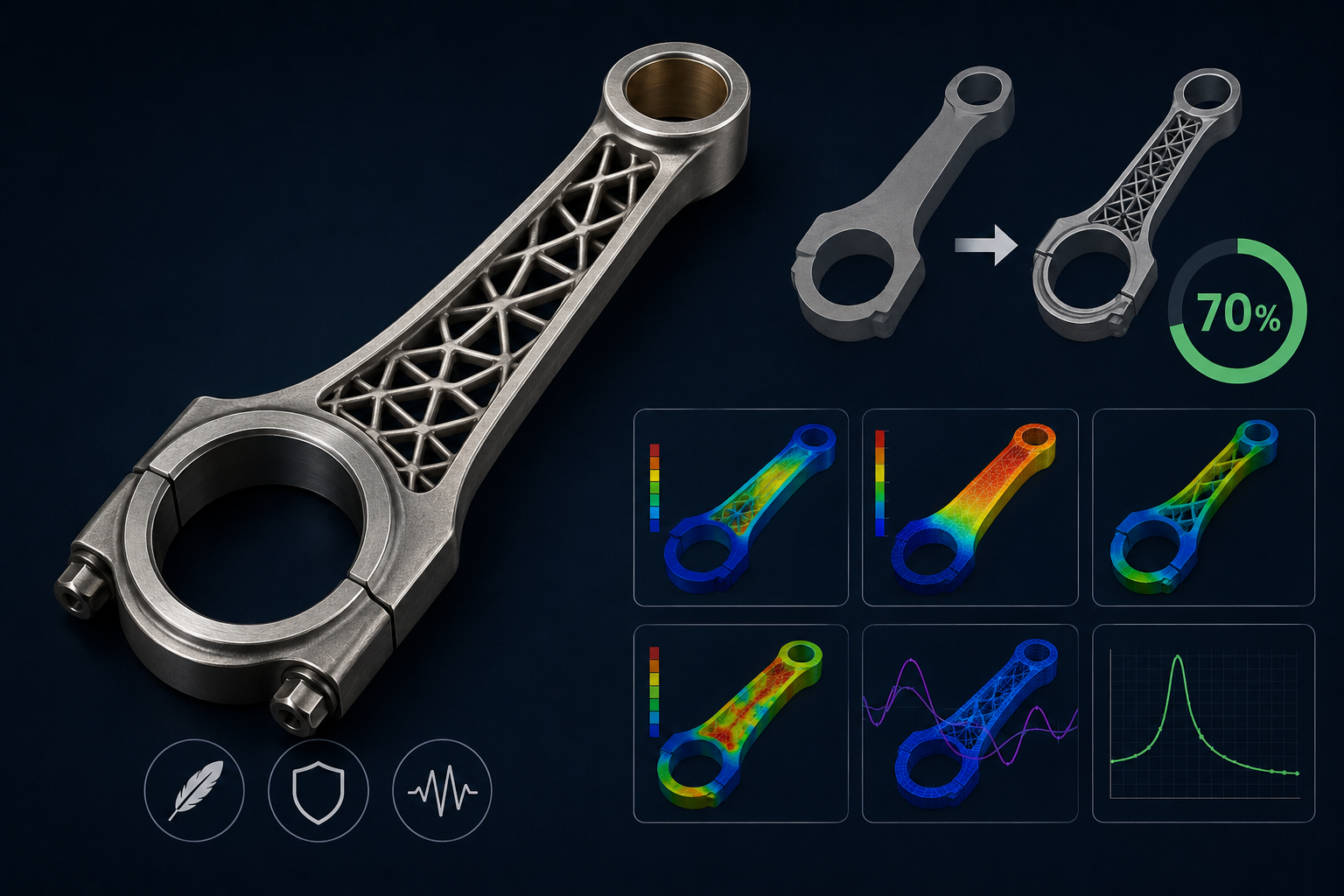
To support the development of the AMPERE Hydrogen Engine, I engineered a high-performance connecting rod designed to reduce mass by at least 20% while adhering to rigorous safety and performance standards. By transitioning from aluminum to stainless steel and implementing a square lattice structure, I achieved a 70% reduction in weight while ensuring structural stability against buckling and vibration-induced stress.
Problem
Hydrogen engines represent a promising frontier for low-emission propulsion, but their components must be optimized for both extreme durability and minimized mass. The primary challenge was to redesign the connecting rod, a critical reciprocating component, to significantly reduce its weight while satisfying three non-negotiable criteria:
- High Mechanical Stress: Maintaining a Factor of Safety (FoS) between 1.0 and 1.2 under peak loads.
- Buckling Resistance: Ensuring structural stability under high-compression conditions.
- Vibration Management: Isolating the rod’s natural frequencies from the engine’s operating range (0–790 Hz) to prevent resonance.
Design Iterations
The optimization process followed a dual-track strategy: Material Selection and Geometric Modification.
Material Evolution
While initial iterations explored aluminum alloys for their favorable weight-to-strength ratio, the material’s lower Young’s Modulus resulted in excessive deformation under peak loads. By transitioning to Stainless Steel, I leveraged a significantly higher Young’s Modulus (193 GPa vs. 71 GPa). This shift enabled a more rigid architecture capable of sustaining higher loads with minimal deformation, despite the material’s higher density relative to aluminum.
Lattice Geometry
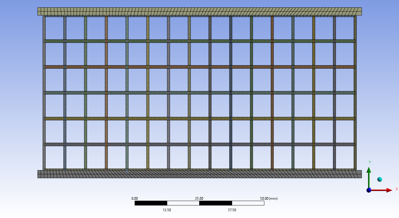
To further optimize the weight-to-strength ratio, I implemented a square lattice structure. This approach replaces solid mass with a repeating cellular geometry. By iterating through 12 distinct configurations, I optimized three primary variables:
- Number of Cells: Adjusting the density of the lattice across the X and Y planes.
- Unit Cell Ratio: Balancing the proportions of the cell walls to optimize load distribution.
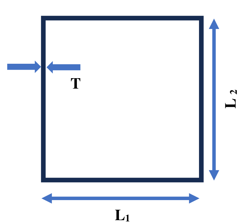
- Wall Thickness (T): Refining thickness to ensure structural integrity while eliminating redundant mass.
 🔍 Click to expand
 🔍 Click to expand
Analysis Performance
To validate the design, I utilized ANSYS for Finite Element Analysis (FEA) and MATLAB for manual verification. The comprehensive testing suite below details the results of these simulations, including stress distribution analysis, buckling stability, frequency response mapping and thermal analysis.
1. Static Structural Analysis (Elastic & Elastoplastic)
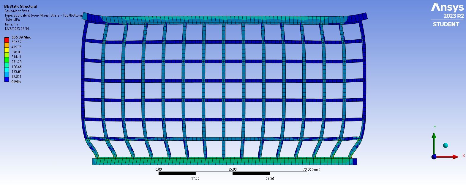
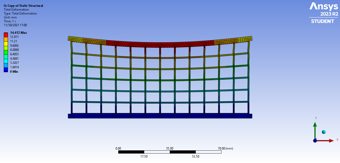
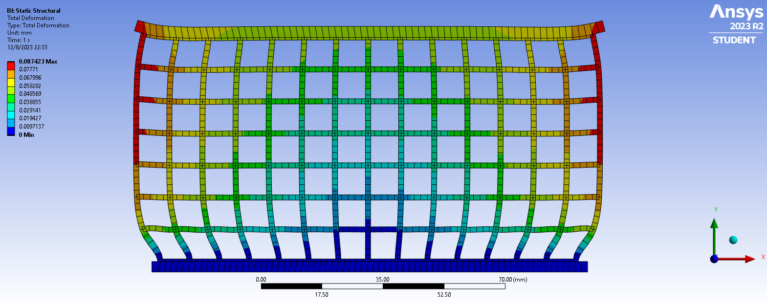
Static Structural Analysis evaluates stress distribution, axial deformation, and structural safety under peak in-cylinder gas forces.
Technical Explanation
To ensure realistic failure prediction, two material constitutive models were evaluated:
- Perfectly Elastic Model: Assumes linear elastic material behavior governed by Hooke’s Law to determine initial yield stress thresholds and linear deformations.
- Elastic-Perfectly Plastic Model: Models non-linear material response beyond the yield point ( 210 MPa for Stainless Steel) to account for localized plastic deformation and stress redistribution.
Loading & Boundary Conditions
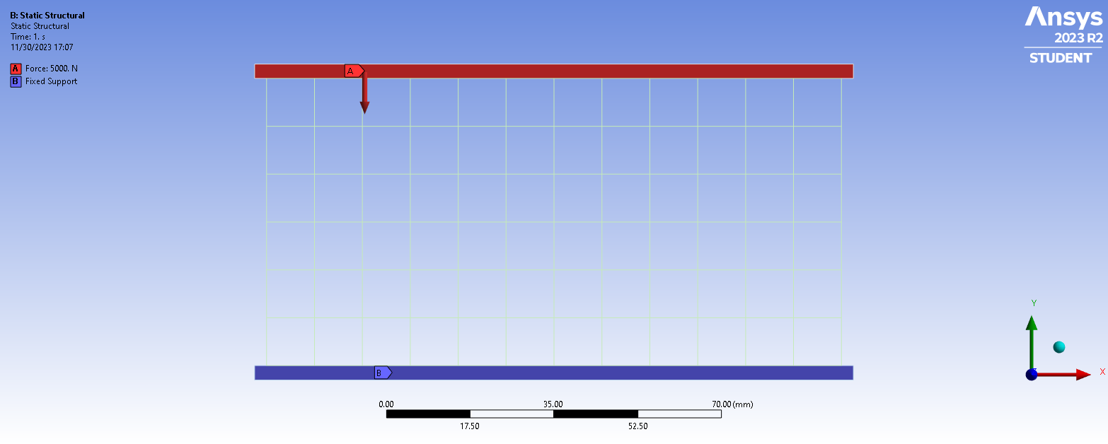
- Applied Load: A static compressive force of 5 kN applied uniformly across the top beam surface.
- Constraints: The bottom beam surface is set as a Fixed Support ().
- Target Criteria: Factor of Safety (FoS) between 1.0 and 1.2. An indicates mechanical yield/failure, while an signifies unoptimized, redundant mass.
 🔍 Click to expand
 🔍 Click to expand
 🔍 Click to expand
2. Eigenvalue Buckling Analysis
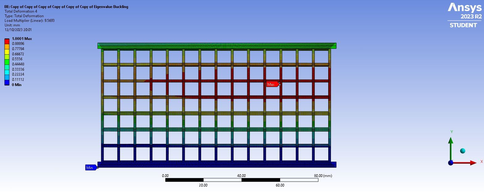
Eigenvalue Buckling Analysis determines the linear structural stability of the slender lattice struts under axial compression.
Technical Explanation
Because lattice structures contain thin-walled vertical and horizontal members, buckling often dictates failure prior to reaching the material yield limit. The simulation solves the eigenvalue matrix equation to determine the Buckling Load Multiplier ():
Both elastic buckling (Euler buckling) and non-linear plastic buckling were evaluated.
Loading & Boundary Conditions
- Boundary conditions remain identical to the static structural setup (5 kN compressive load at top beam, fixed bottom support).
- Target Criteria: Load multiplier . A value of indicates collapse before reaching the maximum operating force of 5 kN.
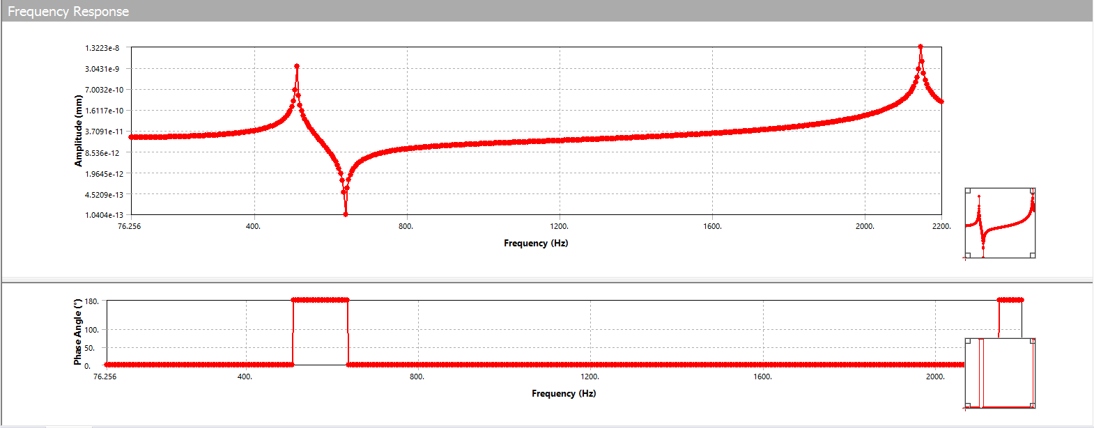
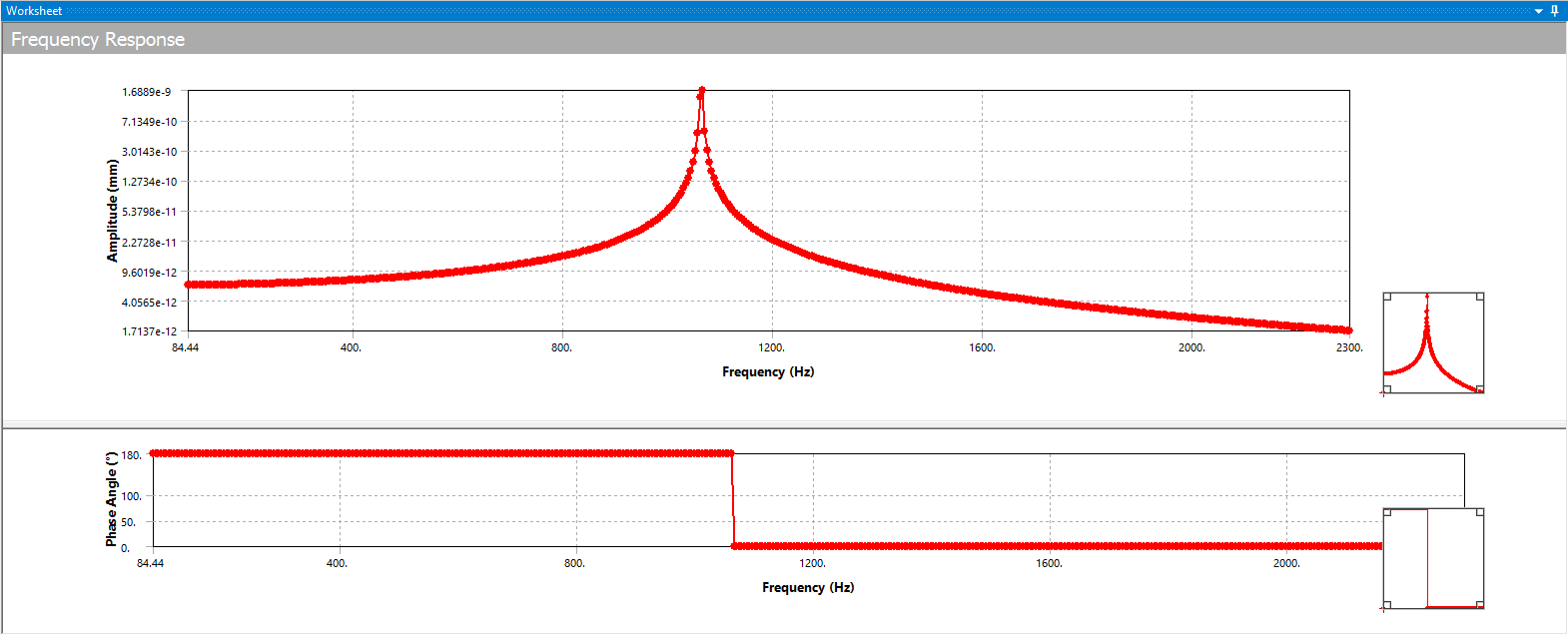
3. Modal & Dynamic Harmonic Response Analysis
Vibration analysis ensures that dynamic operating forces inside the hydrogen engine do not excite the rod’s structural resonances.
Technical Explanation
The dynamic testing regime is split into two sequential steps:
- Modal Analysis: Extracts the first 10 natural frequencies () and mode shapes of the connecting rod to determine baseline resonant frequencies.
- Harmonic Response Analysis: Evaluates steady-state structural response under cyclic sinusoidal forces. The analysis identifies anti-resonance band gaps—frequency ranges where wave attenuation occurs—providing built-in passive damping capabilities.
Loading & Boundary Conditions
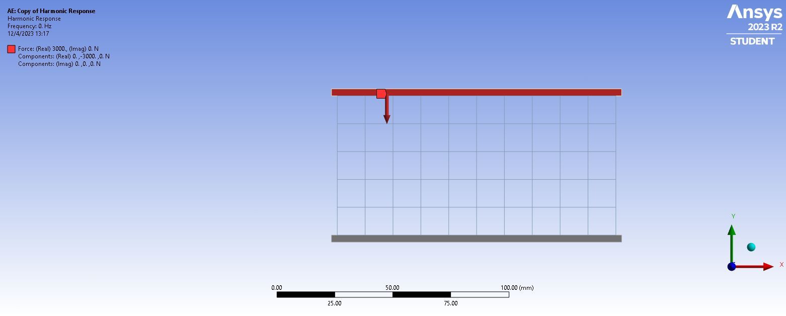
- Dynamic Force: A harmonic sinusoidal force of 3 kN applied at the top beam.
- Constraints: Fixed support at the bottom beam.
- Target Criteria: Complete isolation of structural natural frequencies from the engine operating range of 0 to 790 Hz.
 🔍 Click to expand
 🔍 Click to expand
 🔍 Click to expand
4. Thermal Structural Analysis
Thermal Analysis predicts secondary stresses and distortions resulting from extreme combustion chamber heat.
Technical Explanation
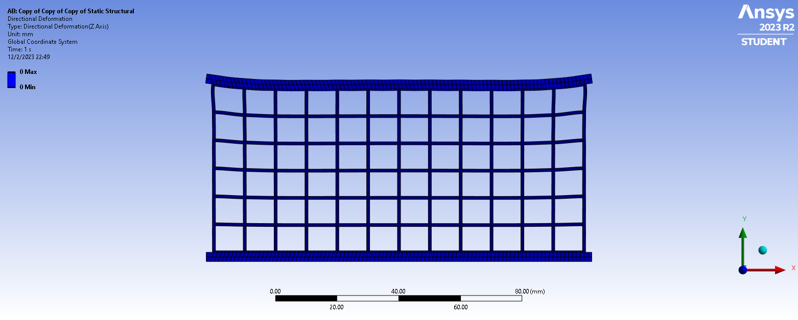
During hydrogen combustion, the connecting rod experiences severe temperature gradients. Stainless steel was selected in part for its high temperature capability (withstanding operational conditions up to ~125°C). The simulation couples thermal expansion coefficients with mechanical constraints to measure Z-axis thermal distortion and residual stress accumulation.
Target Criteria
- Prevent out-of-plane buckling (Z-axis distortion).
- Maintain thermal expansion within allowable engine cylinder clearances.
Key Finding: Stainless Steel exhibited significantly lower thermal deformation than Aluminum configurations, preserving critical dimensional tolerances under thermal shock.
 🔍 Click to expand
 🔍 Click to expand
5. Numerical Verification (ANSYS vs. MATLAB)
To ensure simulation reliability, FEA numerical results were validated against manual calculations in MATLAB using Euler-Bernoulli beam frame element stiffness matrices:
| Analysis Metric | FEA (ANSYS) Result | Hand Calculation (MATLAB) | Error (%) |
|---|---|---|---|
| Normal Bending Stress | Evaluated per configuration | Matrix Formulation | 0.00% (rounded) |
| Axial Strain / Deformation | Evaluated per configuration | Euler-Bernoulli Beam Equations | 0.00% (rounded) |