
TL;DR
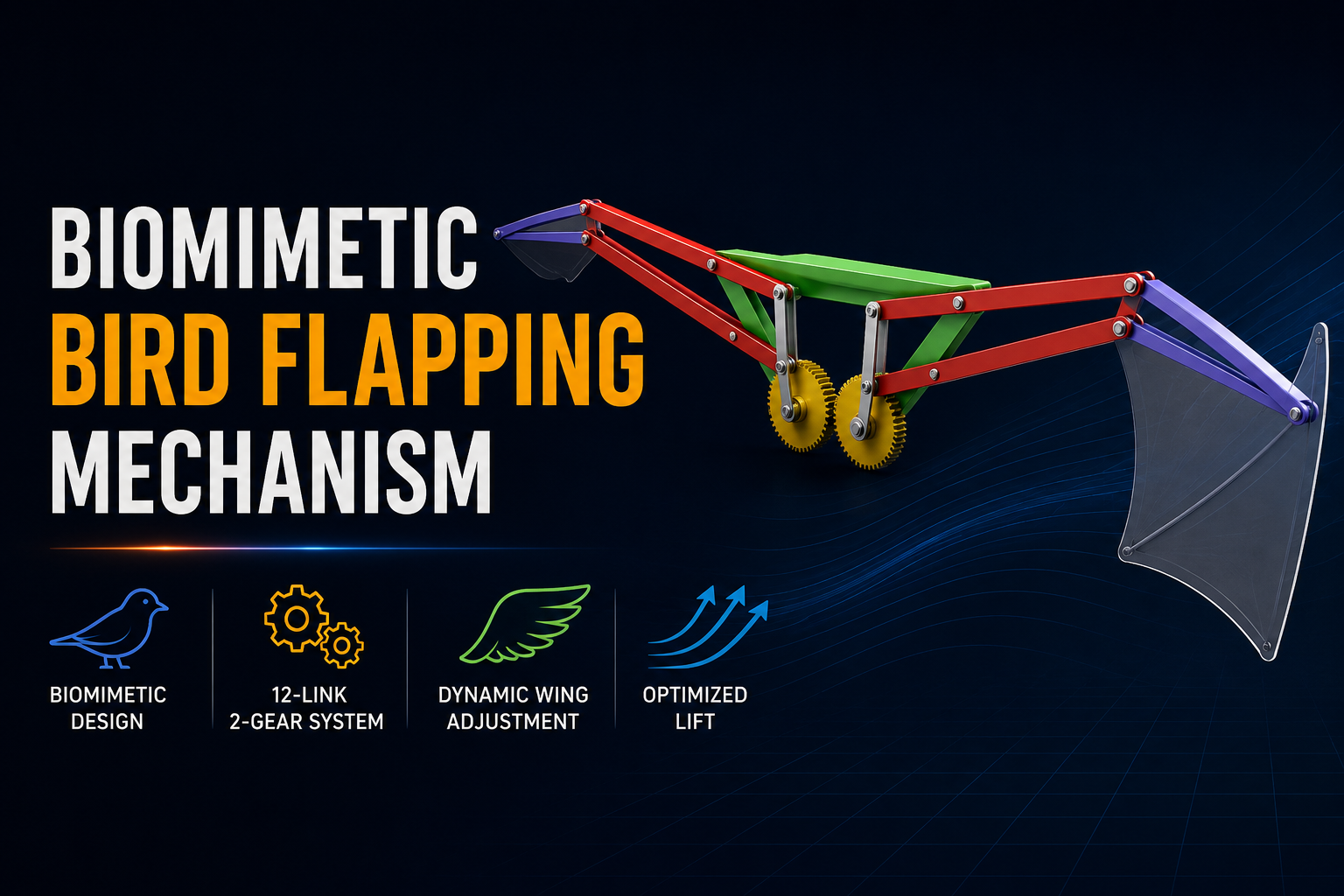
This project explores the field of biomimetics by designing a mechanical system that replicates the complex, non-linear kinematics of avian wing motion. By utilizing a sophisticated arrangement of 12 links and 2 gears, the mechanism translates rotational input into a non-uniform flapping cycle engineered to optimize aerodynamic lift and propulsion.
Problem
Simulating avian flight in robotic systems presents a significant engineering challenge: capturing the complex, non-linear movements inherent in biological wing motion. To generate sufficient lift, a wing must either execute a “quick return” action (accelerating during the downstroke) or dynamically alter its surface area. This project focuses on the latter, dynamic surface area reduction, where the wing folds during the upward stroke to minimize drag and expands during the downward stroke to maximize lift.
Design Iterations
The mechanism was engineered as a multi-stage system where each component serves a specific kinematic function:
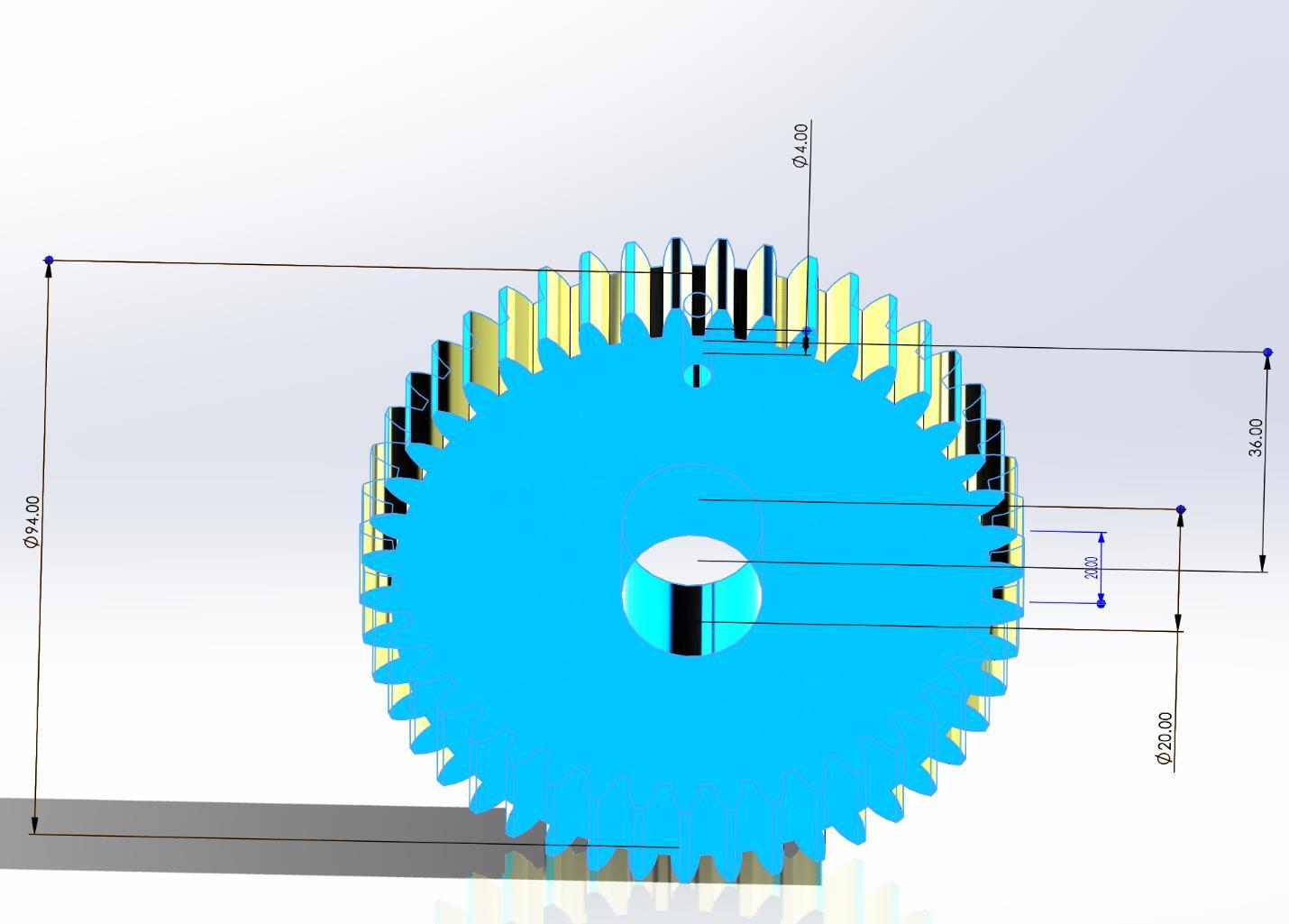
- Power Transmission: A dual-gear system ensures that rotational motion from the motor is distributed evenly, synchronizing the movement of both wings while minimizing backlash.
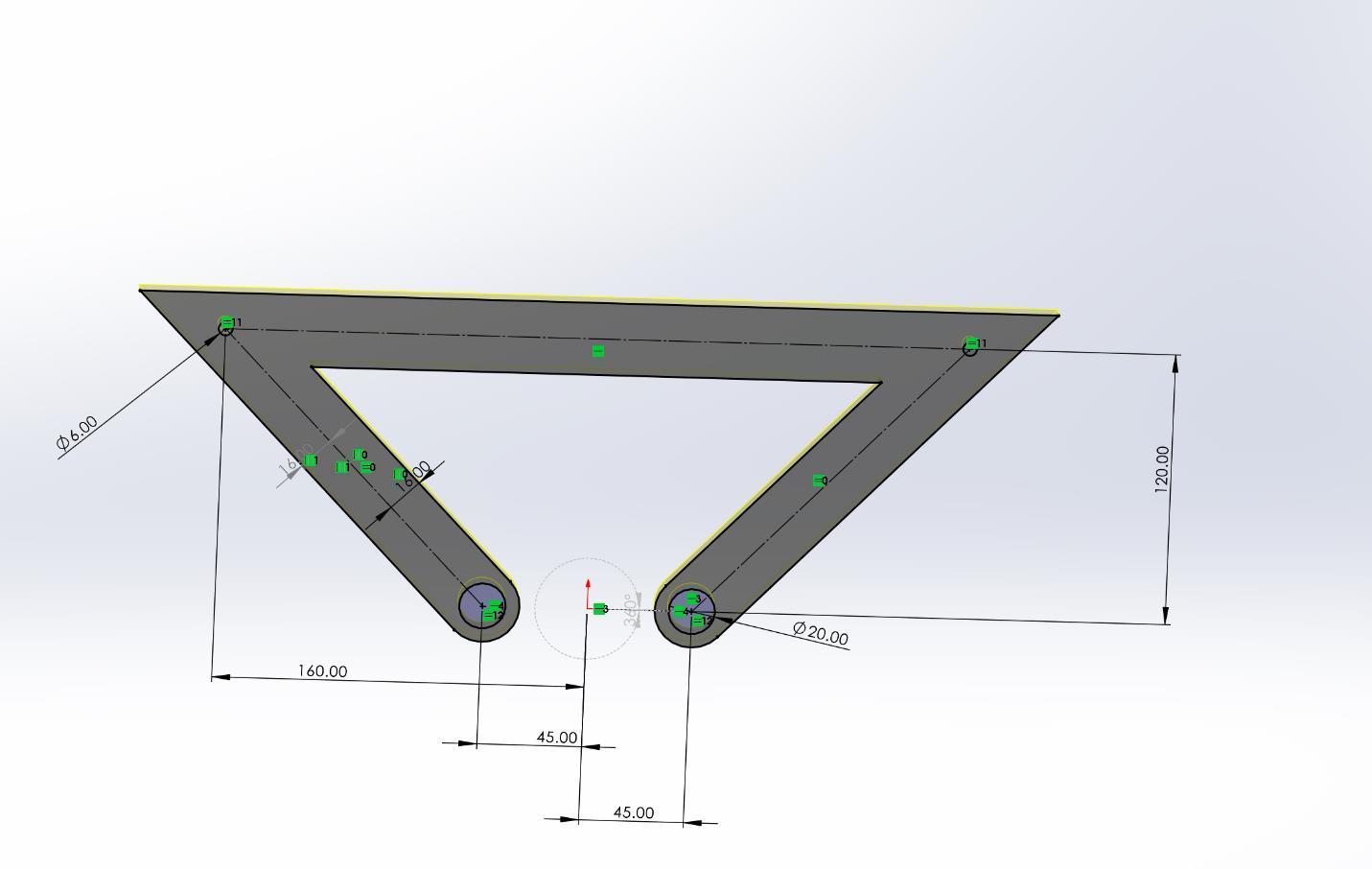
- Structural Foundation: A robust base provides stable mounting points for the linkages, ensuring the center of gravity remains constant during high-frequency operation.
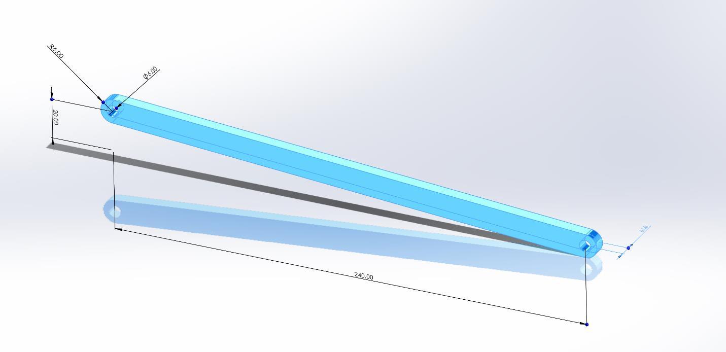
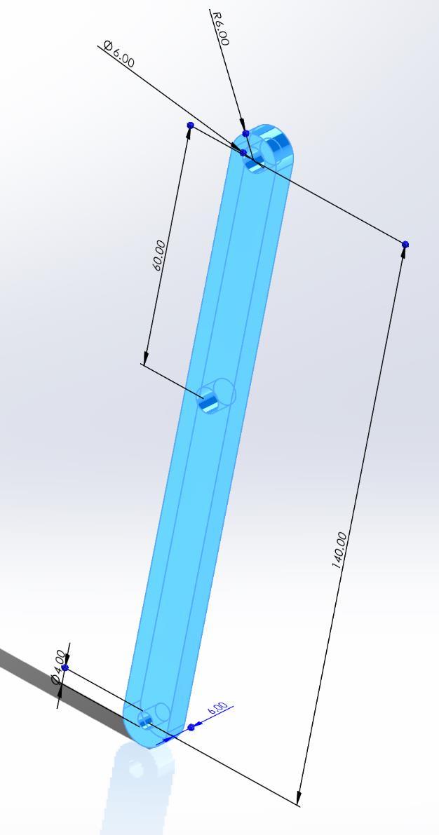
- Motion Conversion: Specialized conversion links facilitate the transition from rotation to oscillation, translating the gear’s circular path into the required flapping amplitude.
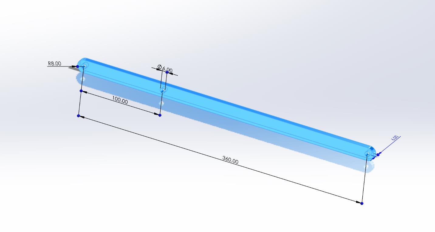
- Primary & Stabilizing Links: The primary links determine the flapping frequency and amplitude, while the stabilizing links provide the necessary constraints to ensure the wing follows a controlled, predictable trajectory.
 🔍 Click to expand
 🔍 Click to expand
- System Integration: The final assembly integrates these components into a cohesive unit capable of mimicking natural wing behavior with high fidelity.
Video Simulation
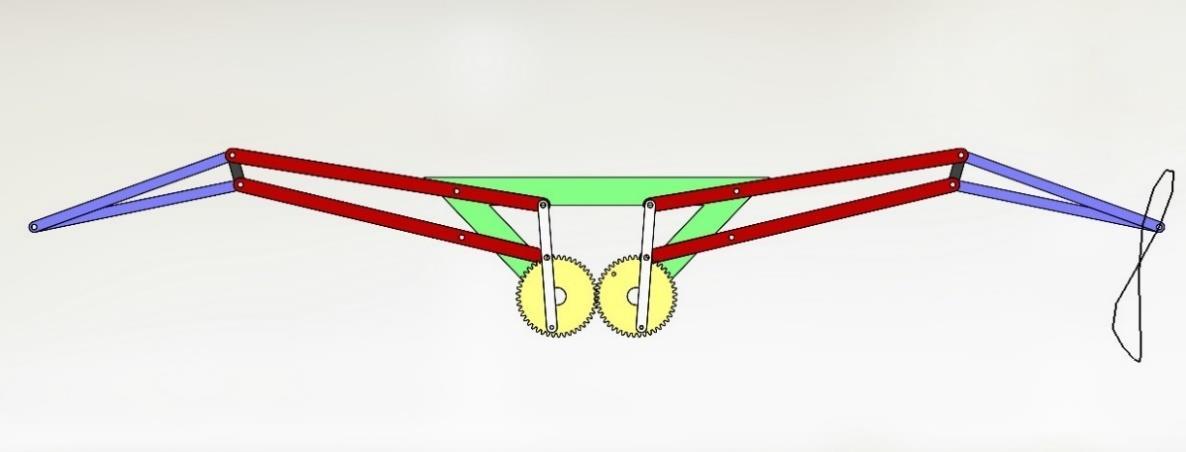
The following video simulation demonstrates the non-uniform motion of the wing tip, highlighting the dynamic surface area reduction during the upward stroke and the expansion during the downward stroke. The simulation confirms that the mechanism achieves the desired kinematic profile, effectively replicating the flapping motion of a bird’s wing.
Technical Details
To validate the design, the system was analyzed based on its ability to manipulate aerodynamic profiles through surface area reduction. This methodology ensures that:
- Top Position: The wing extends to its maximum surface area to capture airflow and generate peak lift.
- Bottom Position: The wing retracts into a streamlined profile to minimize drag during the upward transition.
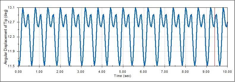
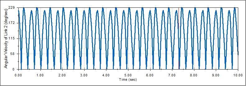
The visual data confirms the non-uniform motion of the wing tip, which is critical for realistic flight simulation. Furthermore, kinematic analysis was performed to map the trajectory and angular velocity. The resulting data confirms that while the motion is non-uniform, the system maintains mechanical integrity across all links throughout the entire cycle.
 🔍 Click to expand
 🔍 Click to expand
Results & Key Metrics
- Mechanism Complexity: Successfully integrated a 12-link, 2-gear kinematic chain into a single cohesive assembly.
- Aerodynamic Optimization: Validated a design that effectively alternates between high-lift and low-drag configurations to mimic biological flight.
- Kinematic Accuracy: Simulation results confirmed non-uniform motion profiles, successfully matching the intended biomimetic requirements for avian wing dynamics.