
TL;DR
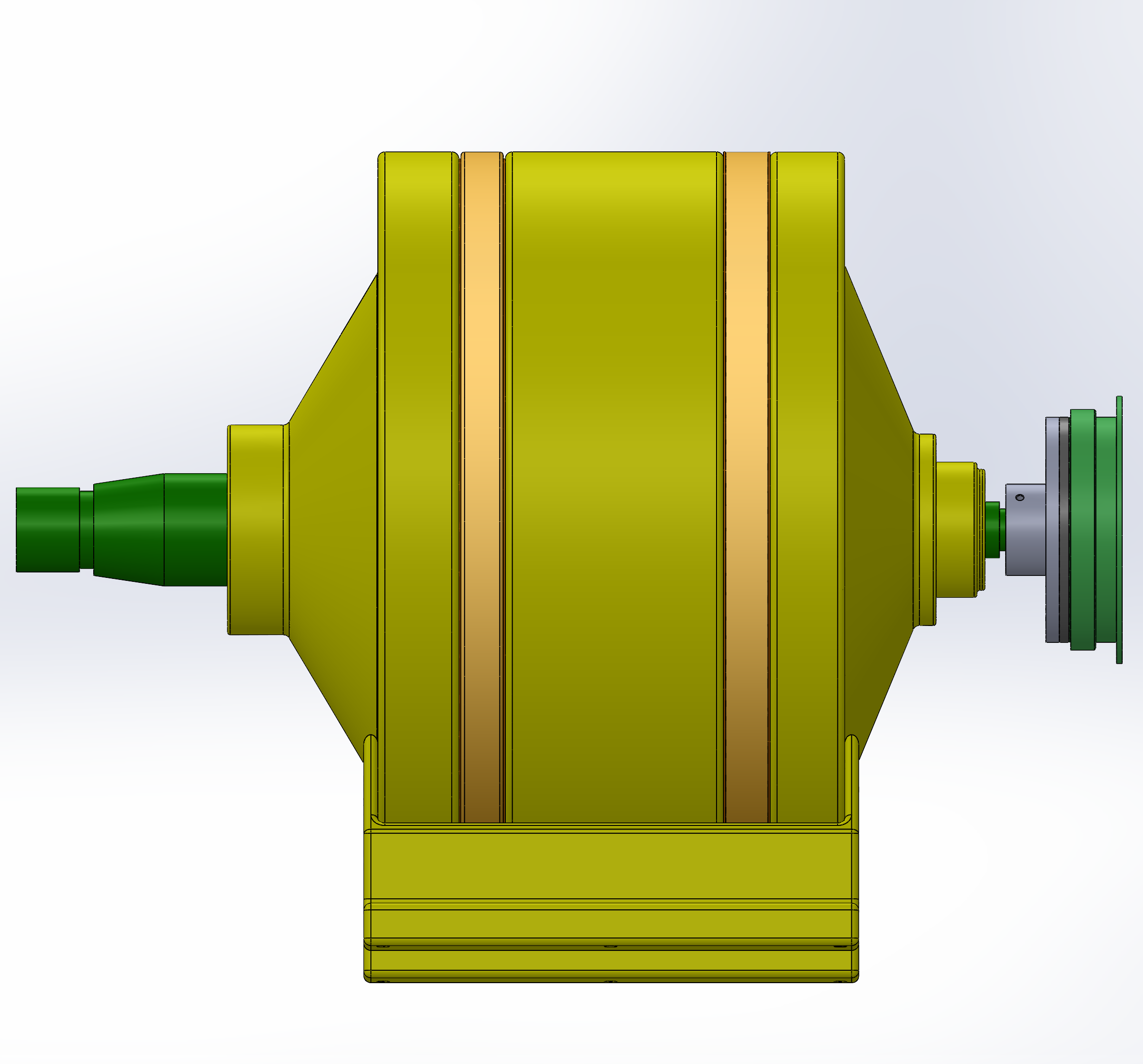
Designed and engineered a robust, two-stage planetary gear train (CPGT) to drive an industrial hoist drum. The system successfully reduces motor speed from 1480 RPM to 67.7 RPM while managing a 1200 N·m output torque, all while operating within a compact housing designed for harsh industrial environments.
Problem
The primary engineering challenge was to develop a transmission system capable of delivering high torque to a hoist drum while maintaining a minimal spatial footprint. To meet the operational requirements of the application, the system had to satisfy several critical constraints:
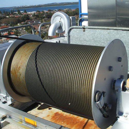
- High Torque Management: Sustain a 6000 N line tension (resulting in 1200 N·m at the drum).
- Spatial Optimization: Utilize a two-stage planetary architecture to achieve a high reduction ratio of 21.86:1 within a compact housing.
- Environmental Durability: Operate reliably in industrial environments with temperatures up to 45°C and high levels of dust and corrosion (IP55/C3).
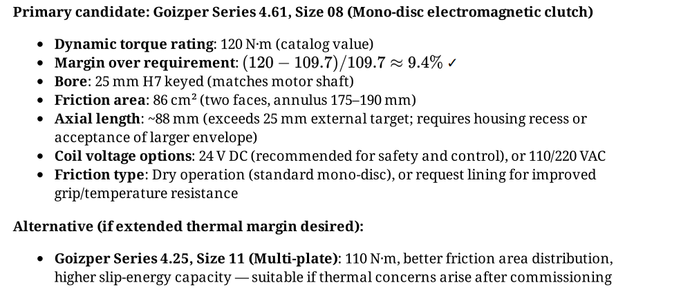
- Safety Integration: Incorporate an electromagnetic clutch for controlled engagement under heavy loads.
Design Iterations
The development process progressed from initial conceptual requirements to a validated mechanical assembly through several critical design iterations:
- Architecture Selection: A two-stage planetary system was selected over a standard spur gear train to maximize power density and ensure precise coaxial alignment between the motor and the hoist drum.
- Gear Geometry Optimization: Utilizing MITCalc, the team iterated on module sizes and tooth counts. A 5mm module with a 10° helix angle was finalized to balance structural strength, weight, and manufacturing feasibility.
- Load Distribution: To manage extreme torque in Stage 2, the number of planets was increased to four, ensuring even load distribution and reducing peak stress on individual gear teeth.
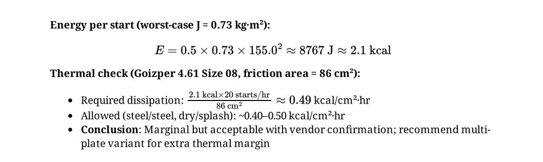
- Component Selection: The integration of SKF-standard bearings and Goizper electromagnetic clutches ensured the system could withstand a demanding 20 starts-per-hour duty cycle.
Technical Details
The engineering of the gearbox was divided into three core technical domains:
1. Gear & Shaft Engineering
 🔍 Click to expand
 🔍 Click to expand
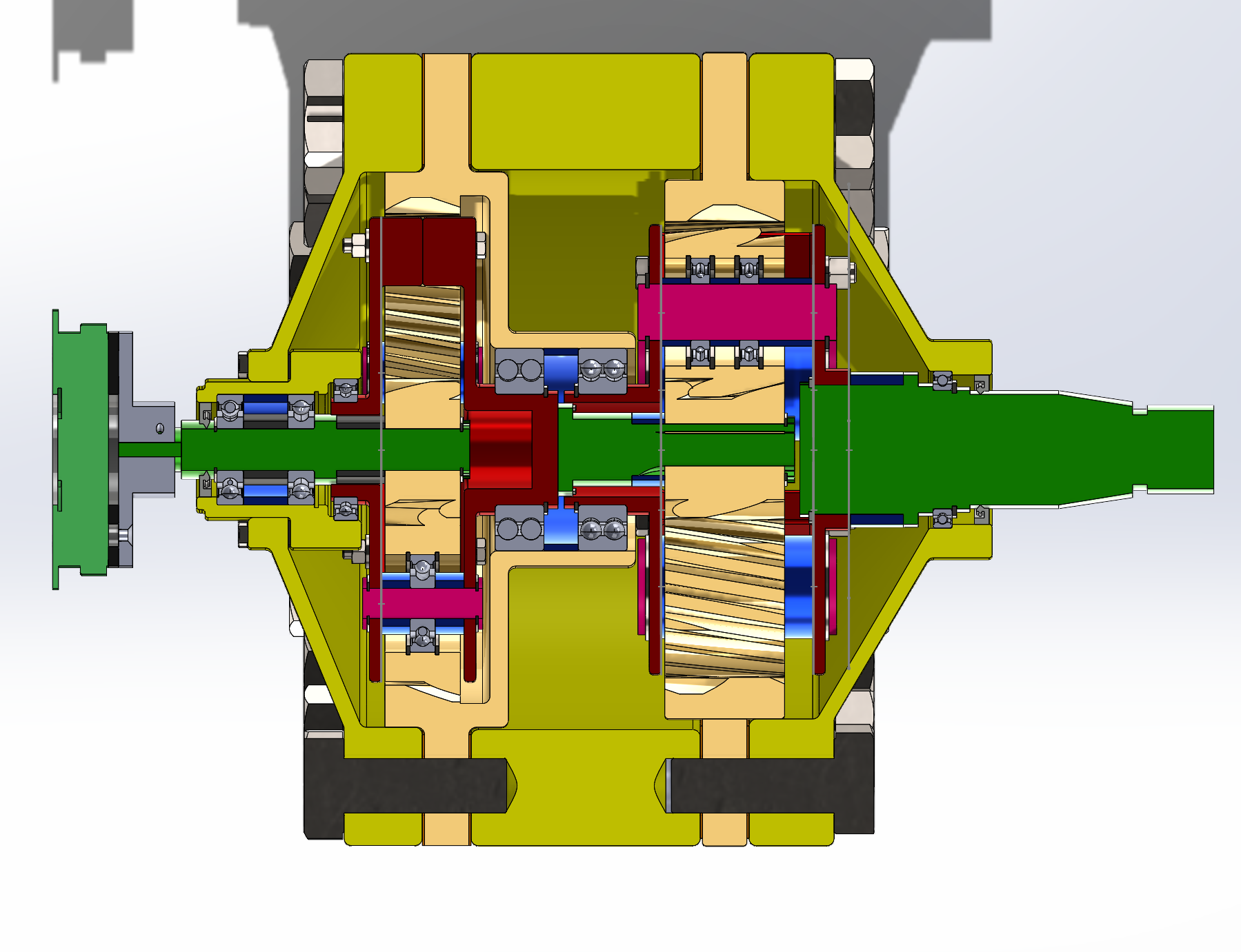
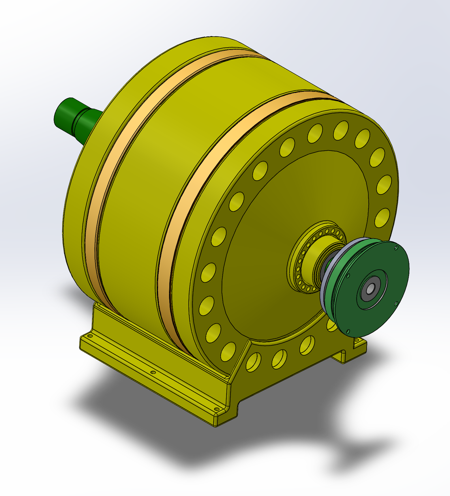
The transmission utilizes a Compound Planetary Gear Train (CPGT) architecture to achieve the required reduction while maintaining mechanical integrity.
- Stage 1: Features 3 planets to manage the initial reduction phase.
- Stage 2: Features 4 planets to handle the peak torque of 1229.8 N·m.
- Material Specifications: Gears are designed for fabrication from AISI 4320 medium-carbon steel with a carburized surface (58–62 HRC) to withstand high contact stresses and industrial wear.
2. Structural & Fastener Analysis
To ensure the integrity of the casing under significant axial thrust and radial loads, a tiered fastening strategy was implemented:
- Internal Clamping: 22 M10 bolts secure the inner casing to manage local stresses and ensure uniform gasket compression.
- Structural Support: 40 M42 bolts provide the primary structural connection between the housing halves and the machine frame, engineered to resist high torque from Stage 2.
- Grounding: 8 M10 bolts anchor the base to the foundation to prevent micro-motion during operation.
3. Clutch & Safety Integration
 🔍 Click to expand
 🔍 Click to expand
 🔍 Click to expand
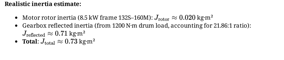
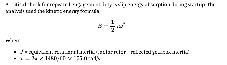
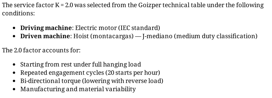
The inclusion of an electromagnetic clutch was validated through a rigorous selection process. Based on Goizper sizing formulas, the clutch was specified to handle a minimum dynamic torque of 110 N·m, providing a safety factor of 2.0 for reliable industrial operation.
 🔍 Click to expand
 🔍 Click to expand
 🔍 Click to expand
Results & Key Metrics
- Reduction Ratio: Achieved 21.86:1 (Target: ~21.8).
- Output Speed: 67.7 RPM (Target: 67 RPM).
- Safety Factor: 2.0 for both clutch engagement and casing load distribution.
- Durability: Designed for IP55 and C3 corrosion classes to ensure longevity in harsh, outdoor industrial environments.