TL;DR
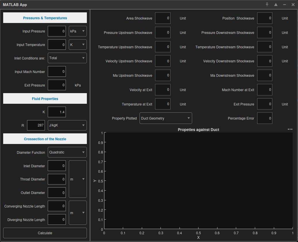
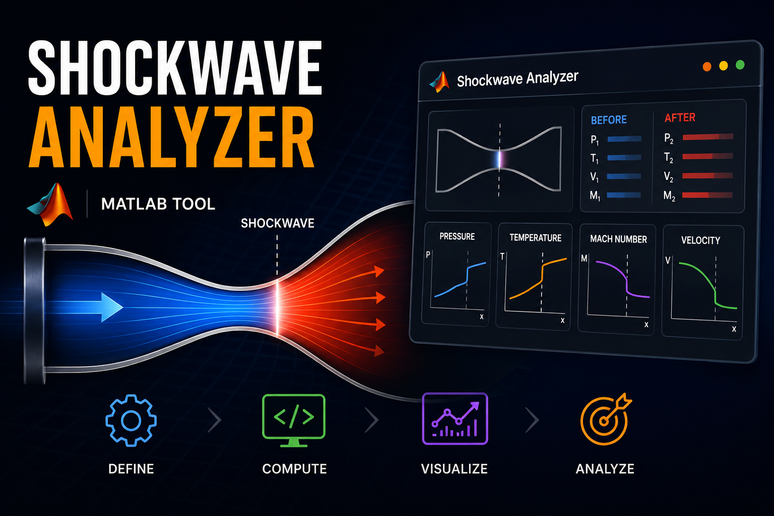
This project features a robust computational tool designed to analyze and predict shock wave behavior within converging-diverging (CD) ducts. By integrating complex fluid dynamics equations into a modular MATLAB environment, the tool enables engineers to simulate various duct geometries, pinpoint precise shock locations, and visualize critical flow properties—including Mach number, pressure, and temperature—in real-time.
Problem
In high-speed aerodynamics, determining the exact location of a traveling shock wave is critical for the design of engines and nozzles. Manually calculating these positions using Rankine-Hugoniot relations and area-Mach relations becomes computationally intensive and prone to error when navigating non-linear duct geometries. Engineers require a specialized tool capable of:
- Handling Variable Geometry: Supporting both linear and quadratic wall profiles to accommodate diverse engineering specifications.
- Automating Iteration: Solving complex transcendental equations for Mach numbers across varying cross-sections automatically.
- Identifying Regimes: Instantly classifying flow into specific categories, such as Venturi, Overexpanded, or Underexpanded states.
Design Iterations
The development followed a modular engineering methodology to ensure both scalability and precision:
- Geometry Modeling: The initial phase focused on the
Duct_Areamodule. We implemented logic to calculate cross-sectional areas based on user-defined “Linear” or “Quadratic” profiles, ensuring that physical geometry was accurately modeled before fluid calculations commenced. - Fluid Property Mapping: A solver utilizing
fsolvewas developed to determine Mach numbers from area ratios. This module calculates the distribution of pressure (), temperature (), and velocity () along the duct, providing a continuous dataset for downstream analysis. - Shock Detection Logic: A core innovation of the system is the iterative “Shock Detector.” By comparing calculated exit pressures against user-defined targets, the system identifies the specific point where a shock wave occurs and calculates the resulting jump in properties.
- Unit Standardization: To ensure industrial applicability, a dual-layer conversion system was implemented to handle both SI and Imperial units seamlessly, allowing for immediate integration into international engineering workflows.
Technical Details
The tool’s architecture is built upon several core computational pillars:
- Area-Mach Relation Solver: Utilizing the relationship between the area ratio () and the Mach number, the system solves for at every point along the duct profile.
- Shockwave Detection Algorithm: The
Shockwave_Detectormodule iterates backward from the exit to locate the precise point where pressure matches target conditions. It employs Rankine-Hugoniot relations to calculate the jump in properties across the shock wave. - Regime Classification (RPC Criterion): The
SWcheckmodule implements a logic gate to determine the flow regime based on the pressure ratio at the exit (). This allows users to instantly identify if the duct is in a Venturi, Overexpanded, or Underexpanded state. - Automated Visualization: The
Properties_Plotmodule dynamically generates high-fidelity graphs for Mach number, pressure, and temperature, providing a comprehensive visual map of fluid behavior.
Results & Key Metrics
The final tool provides a high-fidelity analysis of internal flow dynamics:
- Precision Mapping: Accurately calculates , , , and at both the throat and the shock wave location.
- Automated Detection: Pinpoints the exact index of the shock wave within the duct’s geometry, removing manual calculation errors.
- Multi-Regime Support: Correctly identifies and displays five primary flow regimes (Venturi, Overexpanded, Underexpanded, Shock at Exit, and Standard Shock).
- Versatile Geometry: Supports both linear and quadratic profiles to accommodate complex engineering designs.
Gallery
The following visualizations demonstrate the tool’s ability to map fluid properties and identify shock locations across various configurations.